|
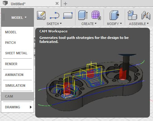
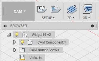
I will be practicing using the CNC Mill by fabricating a sketch of widget 14 shown below using a subtractive process. 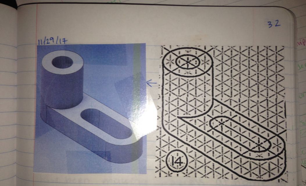 Step 1. Create Widget 14 from the sketch given in Inventor. (To do this use skills learned from Inventor Unit/results in picture above on the left). Then open your Inventor Widget 14 file in Fusion 360. Change setup to "CAM" and click the first icon above "setup." Change your units to inches.
Step 2. Go to setup... 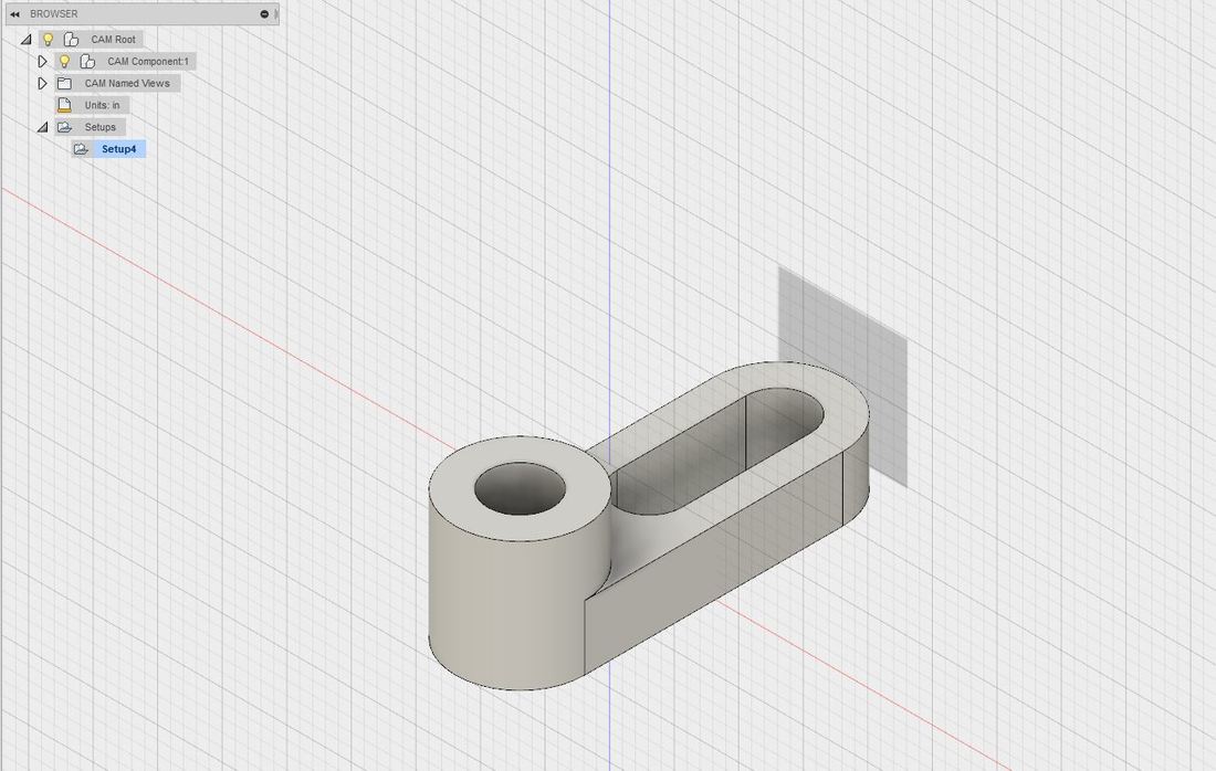 Below is how you want your axes to look, eventually. It may take some clicking around to get the axes how you want them by changing the orientation a few times (under work coordinate system/WCS). 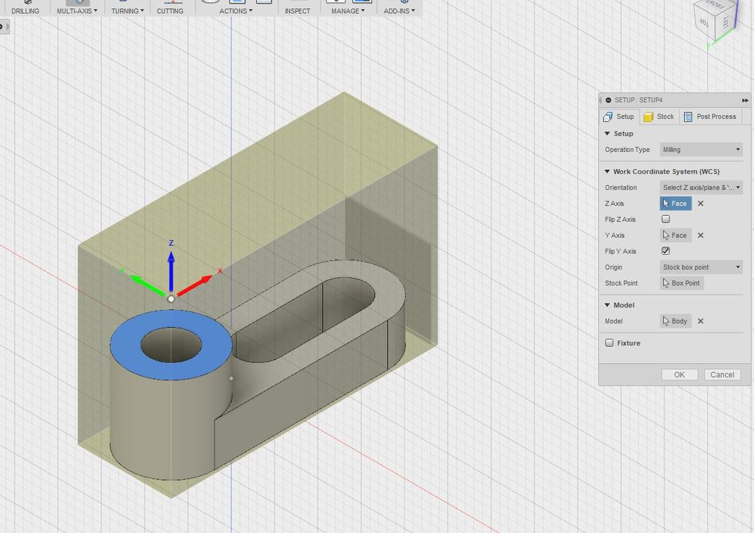 Step 3. Go to "2D Adaptive Clearing," select "tool," and click on the first +tool icon in the the upper righthand of the select tool window that comes up to create a new tool. Select Flat end mill under "Type," and under "Cutting Edge" and "Lengths" specify .25 in for "Diameter," .25 in "Shaft Diameter," .5 in "Flute Length," .75 in "Shoulder Length," 2.25 in "Body Length," and 2.25 in for the "Overall Length." 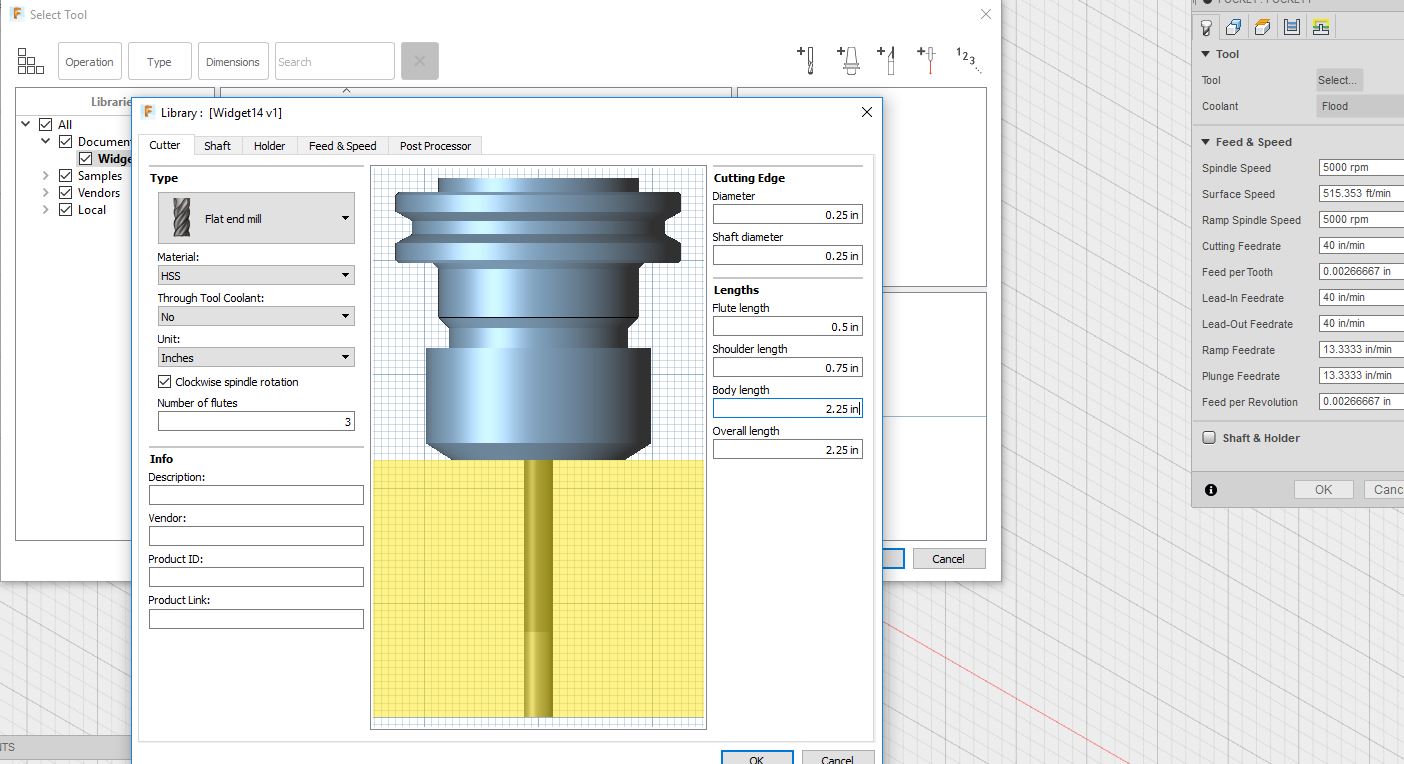 Step 4. Select "Pocket Clearing" under the 3D Icon, and select the fourth icon at the top of the window that shows up ("Passes"). Make both "stock to leave" 0 in. 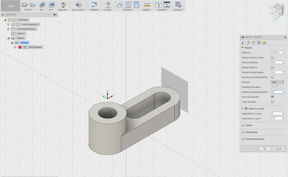 Then go to the second icon at the top ("Geometry") and select these three edges shown. This will tell the mill which inner "holes" to cut out. 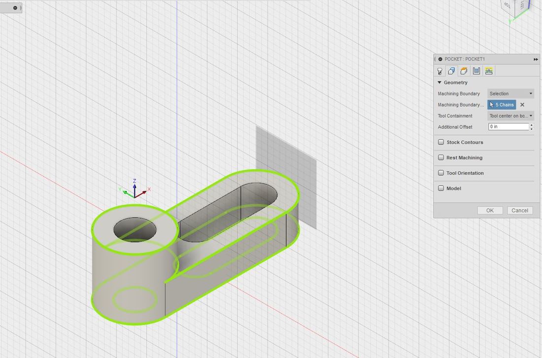 Now click "ok" and these toolpaths should appear. 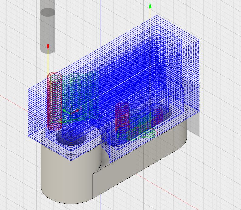 Step 5. Go to "Actions," "Simulate," and click the play button to make sure the pockets are cut out the way you'd like them to be. You can increase the speed by sliding the dot under the play button all the way to the right. 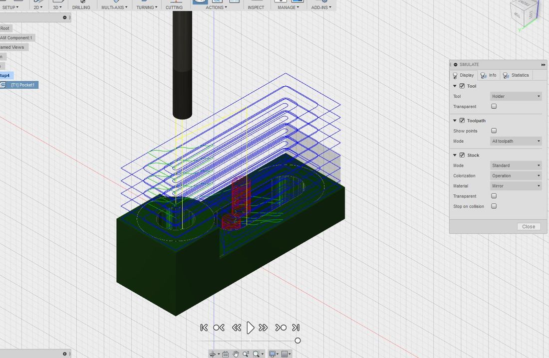 Step 6. Go to 3D and select "Adaptive Clearing" and click on these faces under the same "Passes" icon as before. 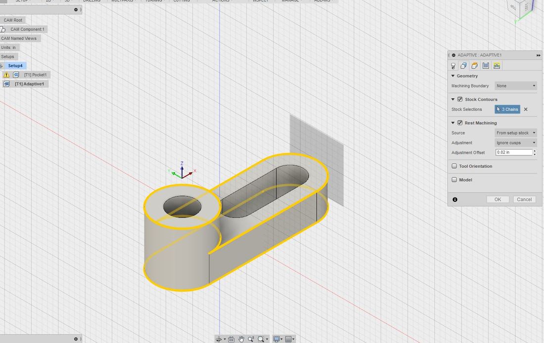 After clicking Ok, your new paths will appear that will tell the mill to cut the outer curves of the widget. 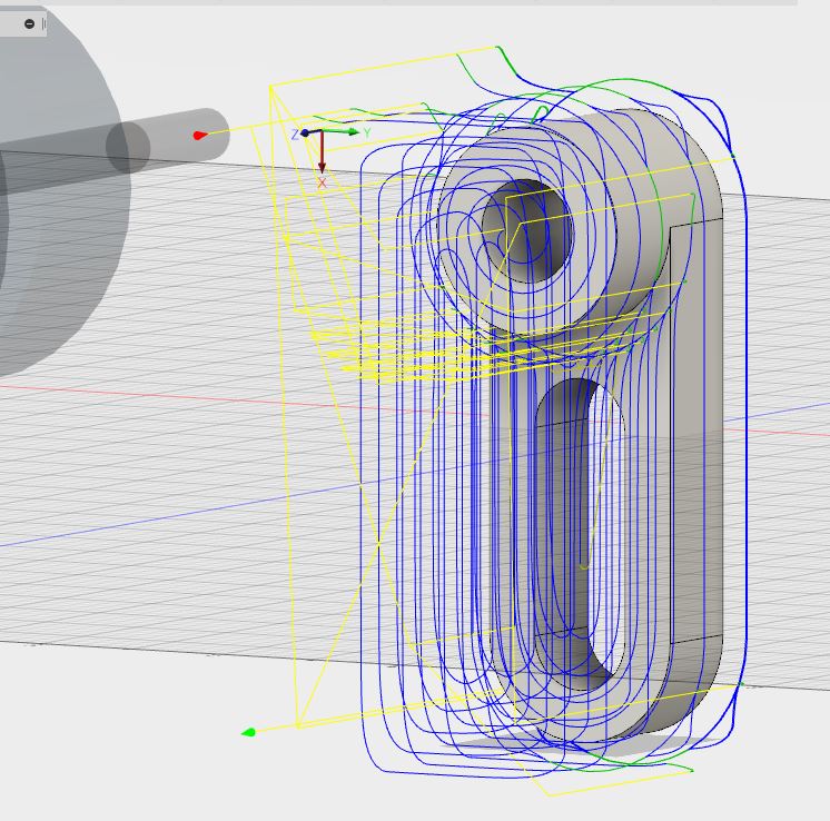 Now perform a simulation like you did in Step 5 to make sure everything will be cut out properly. 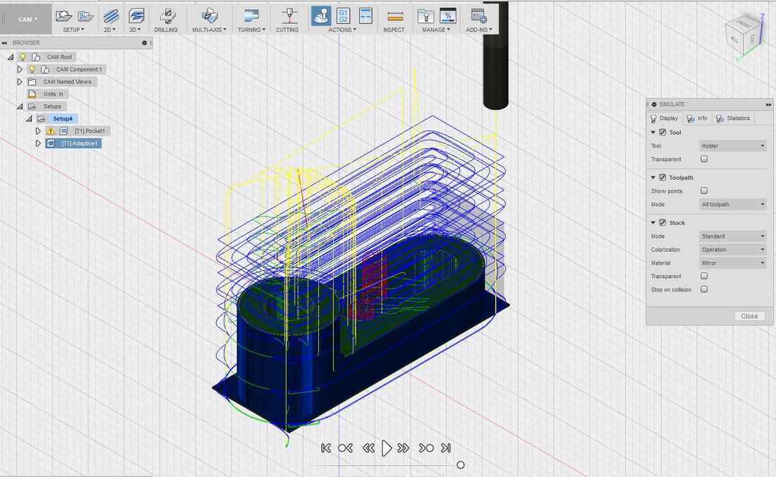 Step 7. Once your toolpaths are satisfactory, go to "Actions" again and select post process... 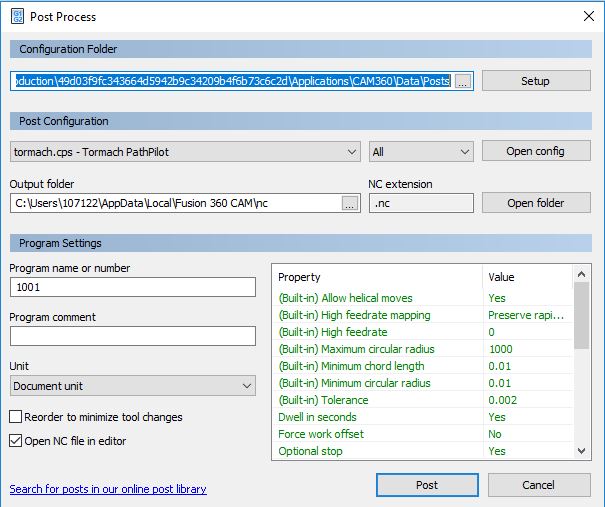 ...click "post." The window shown below which is hundred of lines of g-code will appear that will tell the CNC Mill every movement/cut it needs to perform in order to subtract the correct amount of material from the Styrofoam block you will provide. Save this gcode to a flashdrive. 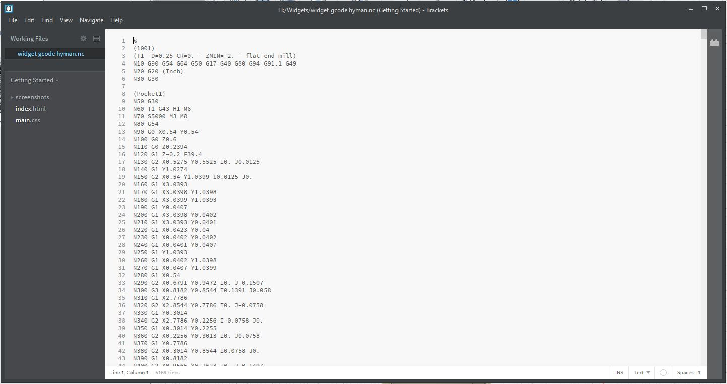 Step 8. Here my classmate had applied a strip of double sided tape to the long bottom edge of a block of Styrofoam that was cut at at least a length of 3 inches. 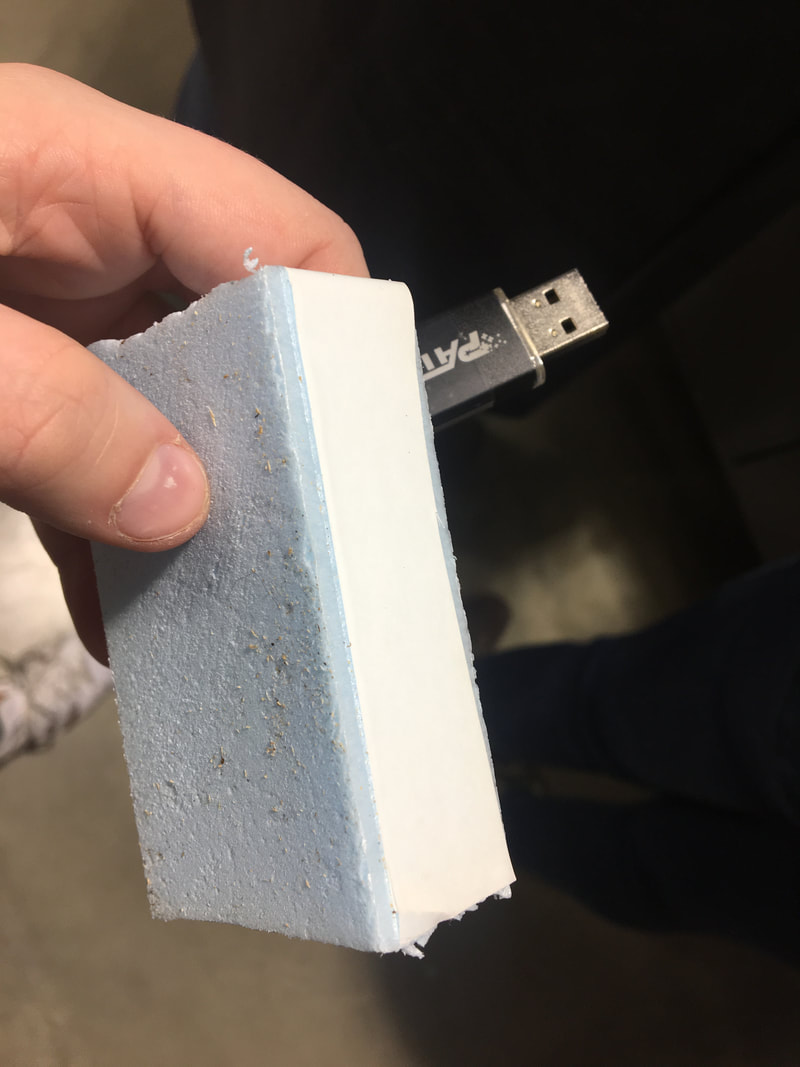 Step 9. Stick the block to the corner of the mill's platform closest to the you, in the left corner. Try to line it up as precisely as possible. If someone has used the mill before you you may need to brush the surface off to remove any left over foam shavings. 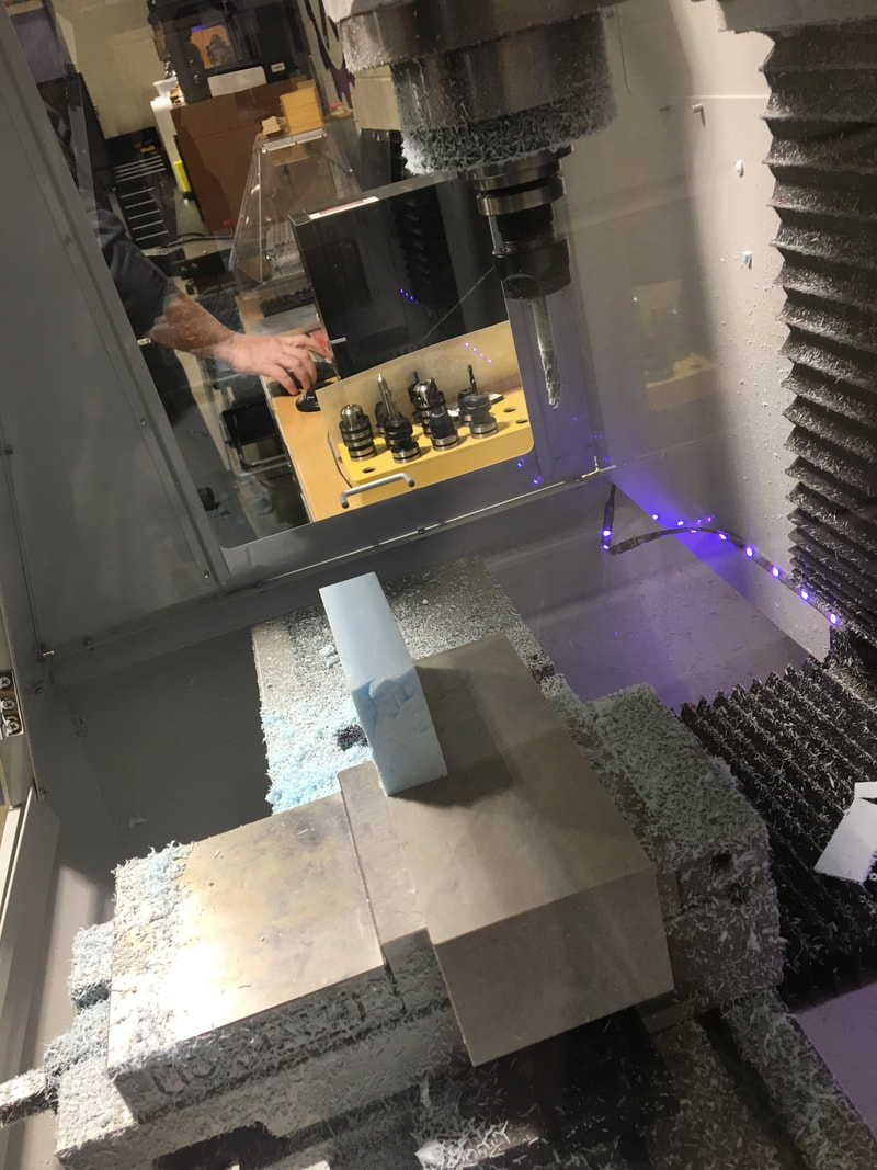 Step 10. Go to the computer that is hooked up to the mill and after plugging in your flashdrive, find your gcode file and open it. 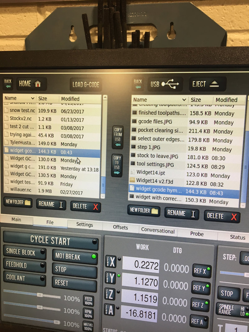 Below is the window that should appear, showing all of the toolpaths you created in Fusion 360.  Step 11. Using the mouse you can move the position of the bit on the mill. You want to use the outer loop to move fast, the inner circle to move with smaller increments, and selecting x-y o move left and right and x to move up and down. The position you are trying to reach the the farthest lower left hand corner of the block. 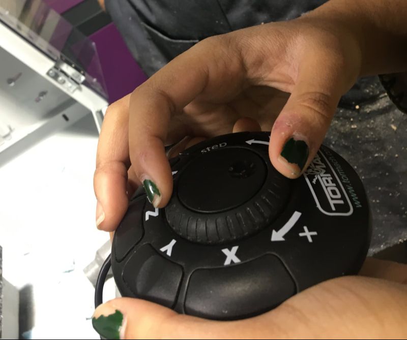 Step 12. Once the bit has reached the ideal mark, you can zero all x,y, and z... 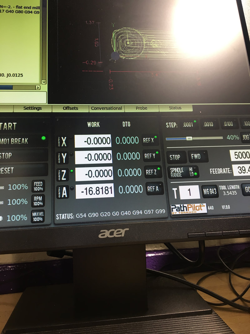 Step 12. After shutting the doors to the mill you can click Cycle Start and let the mill begin. Note: If at any time something goes wrong you can always hit the space bar to abort. hen it was finished, I used a putty knife to GENTLY remove the finished widget. It is a really strong adhesive on a fragile piece of Styrofoam, so be cautious. 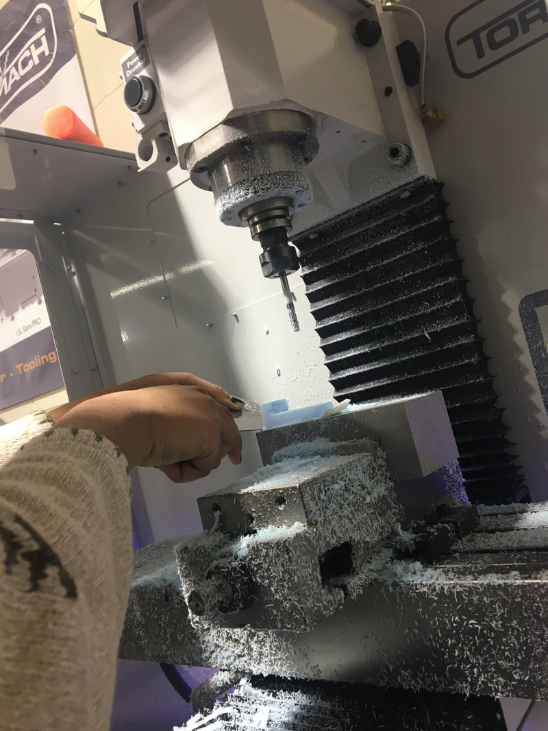 Here is the finished widget: (You can see that one edge looks like it was cut of, this is just due to the block of Styrofoam not being wide enough to start with. I'm pretty confident if I tried to created the widget with wood it would turn out fine.) 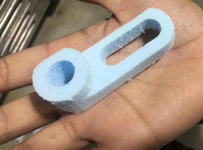 What I Learned.From this project, I learned how to use the basic 3D Adaptive Clearing and 3D Pocket Clearing tools in Fusion 360 and gained a better understanding of how g-code is formed and communicated to computing machinery such as the CNC Mill. I now have a better understanding of how the computer program Fusion 360 works and feel more confident in using it next for my CNC Router project. I still have a bit more to learn about how to adjust the axes of my part files in Fusion 360, and shortening the run time of the cutting process.
0 Comments
|
CNC MillCNC milling, the most common form of computer numerical control (CNC) machining, performs the functions of both drilling and turning machines. CNC mills are categorized according to their number of axis and are traditionally programmed using a set of codes that represent specific functions."- Plouse Manufacturing What is Fusion 360?It is a cloud-based CAD tool for collaborative product development. Fusion 360 combines fast and easy organic modeling with precise solid modeling, allowing you to make manufacturable designs.
ArchivesCategories |
 RSS Feed
