|
Here is my task:
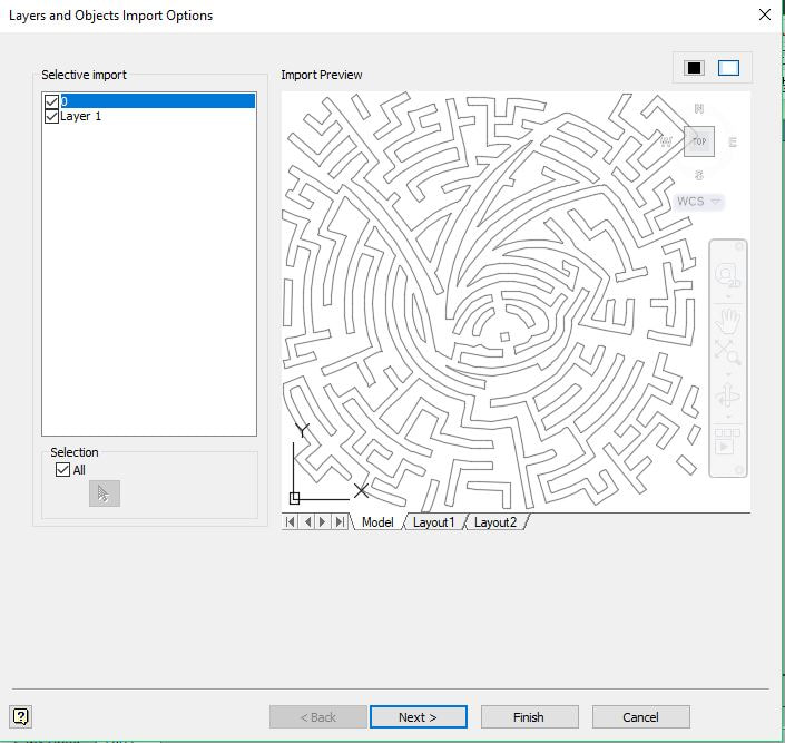
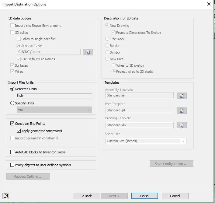
I immediately thought of the maze from the Series of Unfortunate events book/TV series and decided to just replicate that maze. However I was having trouble tracing the image in Inventor an drawing all of the paths myself, so I did a little research and found a way that you can use Illustrator and Inventor together to create a 3d maze part file. Preparing the Image in IllustratorFirst I imported my VFD Maze stencil into Illustrator, select the image and set its dimensions to those I wanted for my maze. I did mine 8" by 8". Then click image trace. Once I traced my image, I went to export, and exported the file as a DWG (or Drawing file). 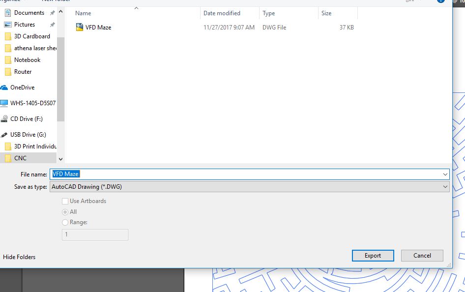 Extruding the Image in InventorNow I go into Inventor and import the DWG file.
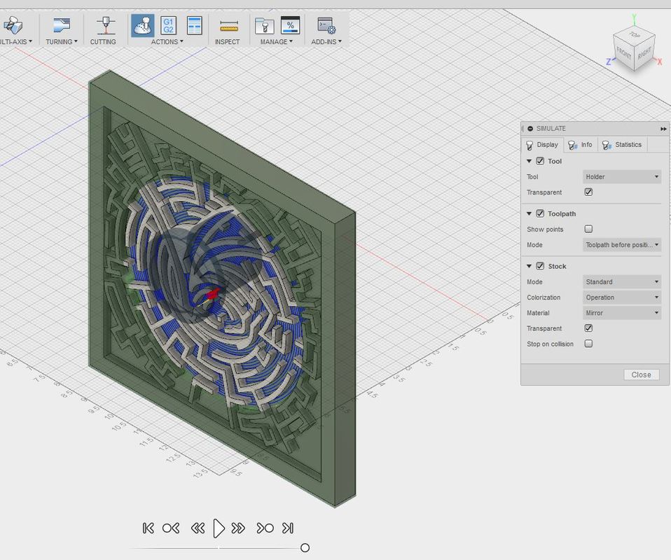
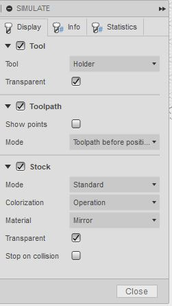
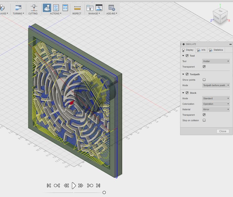
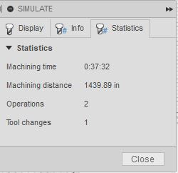
Then I extruded the image 0.25". 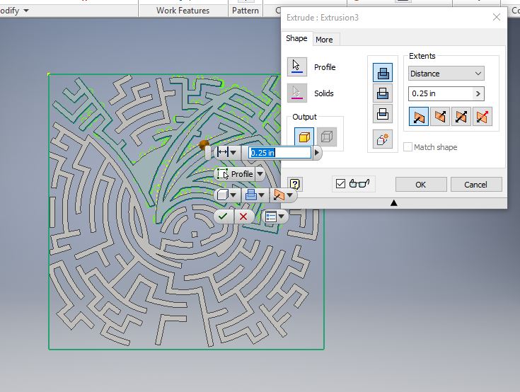 I then flipped the drawing to the back and sketched an 8" by 8" square. 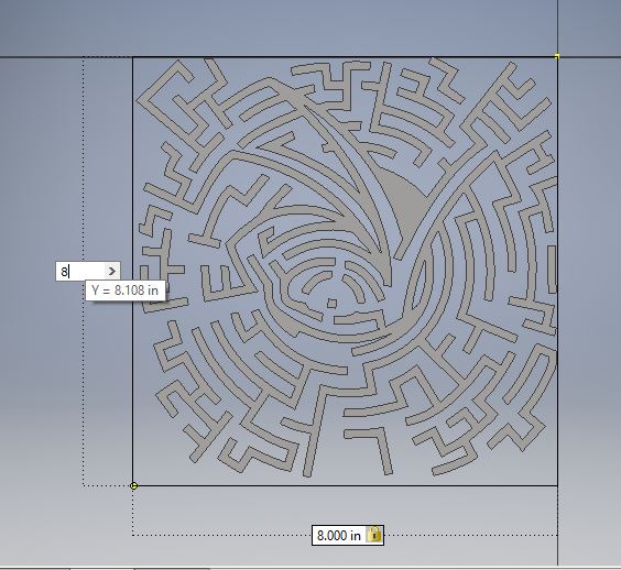 Then I extruded this 8" by 8" square 0.5 inches, making sure to select the "new solid" icon. Now the total thickness of my maze is the maximum 0.75 inches. 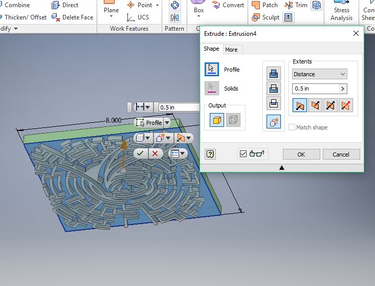 Next I start a new sketch and draw a 0.5 inch border around the entire maze and extrude it .75 inches. 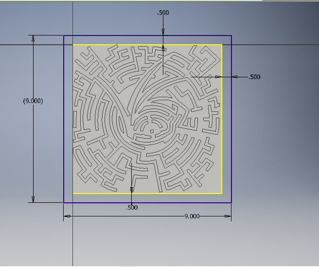 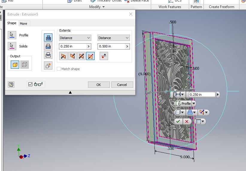 Here is my finished VFD Maze part file. I saved this file to my drive. 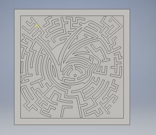 Creating Toolpaths in Fusion 360Now I can open the VFD Maze part file in Fusion 360 (See CNC Mill for more info on Fusion 360). The first thing I do any time I open Fusion 360 is to change my units to inches (it will always default to mm). 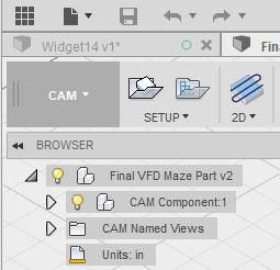 Make sure the upper left corner reads CAM before you begin building your toolpaths. 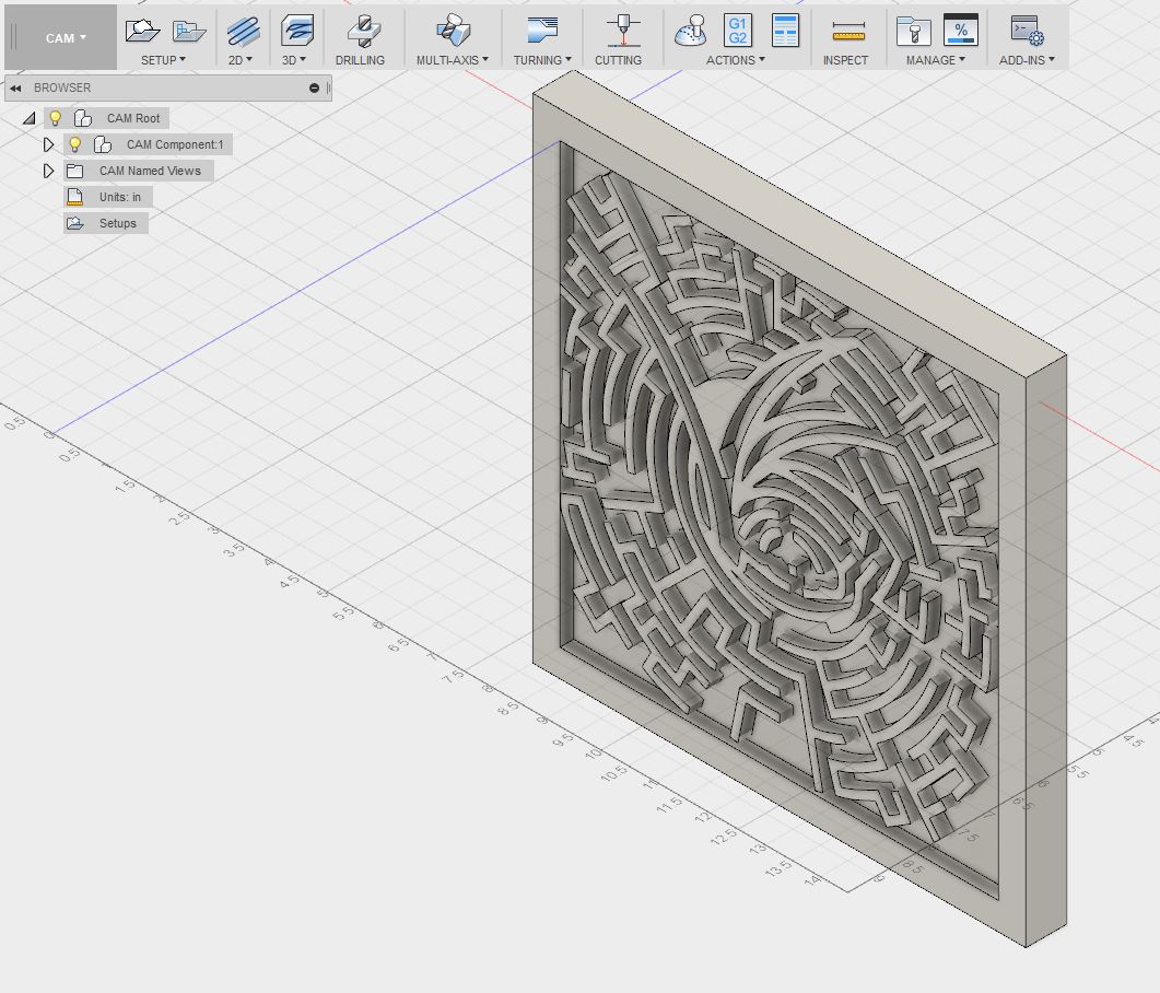 I went to "2D" and selected "Adaptive Clearing." Go to tool and click the first toolpit icon with a plus sign to the left of it to make a new tool. This is specific to the CNC Router so the dimensions should have a 1/8 diameter on a flat end mill. 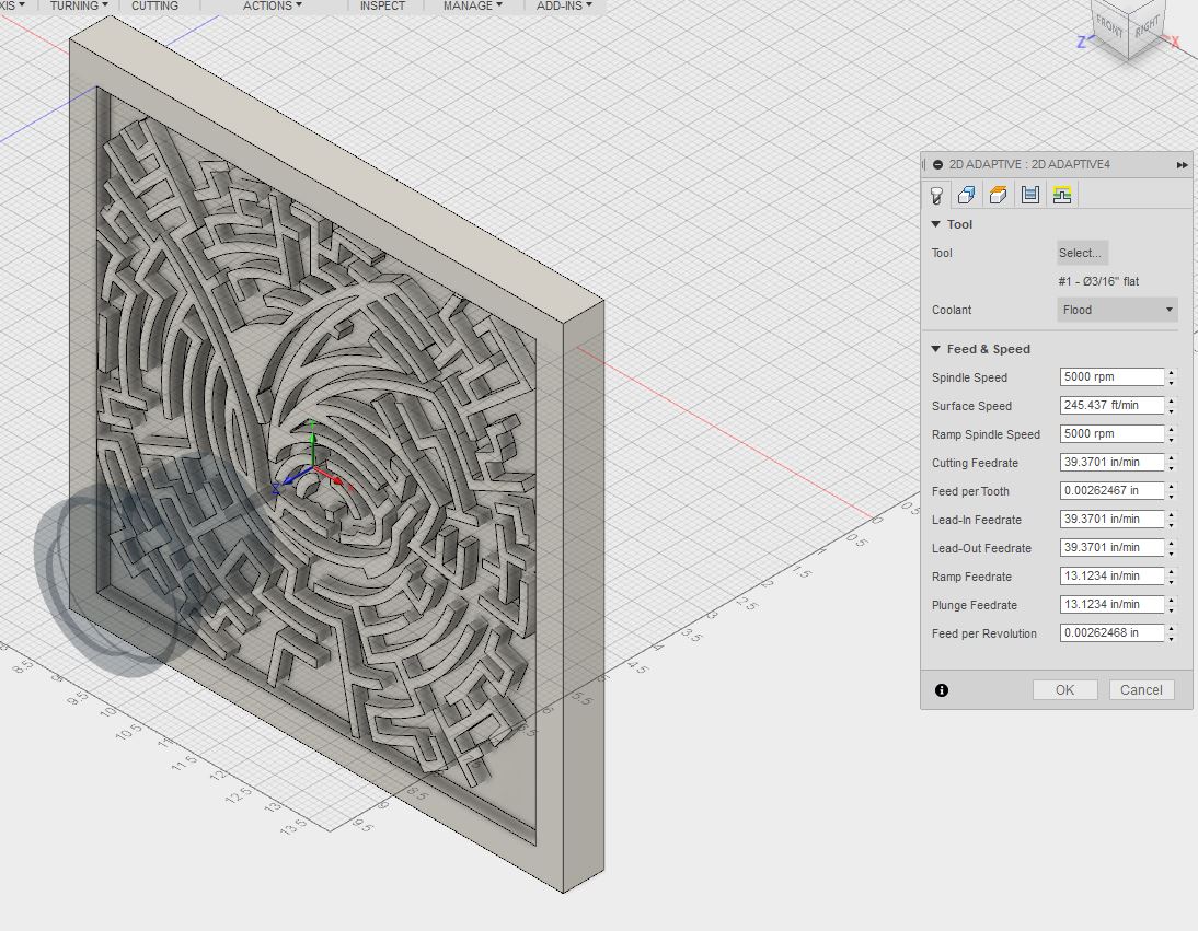 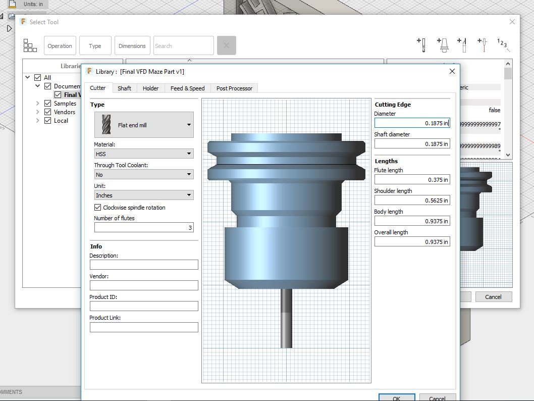 Then I went to tool orientation under the "geometry" icon. Luckily my tool orientation was already set up correctly, but if not I could have just selected my z axis (more details on CNC Mill). 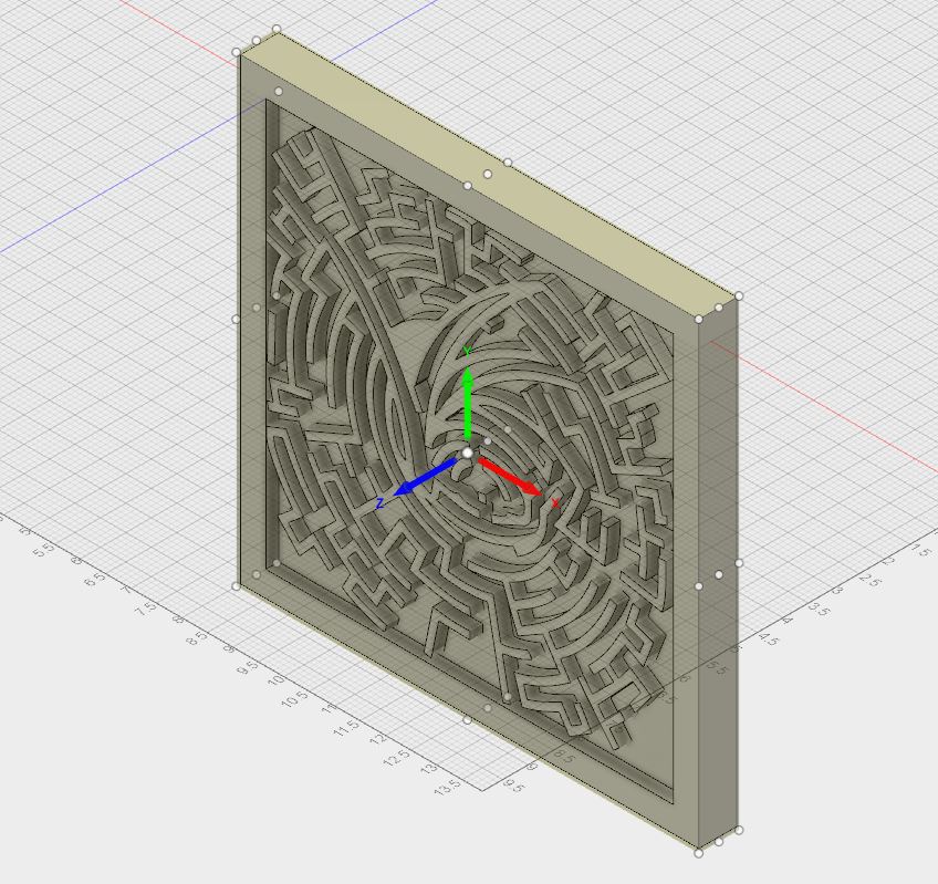 Then, still in Adaptive Clearing, under geometry I simply select the "bottom floor" of the inside of my maze. This will essentially tell the router to clear out this space. Once I click ok, the toolpaths will form. *Also, I went into "passes" and made all stocks to leave 0 so that the router doesn't think there is more material available than there actually is. 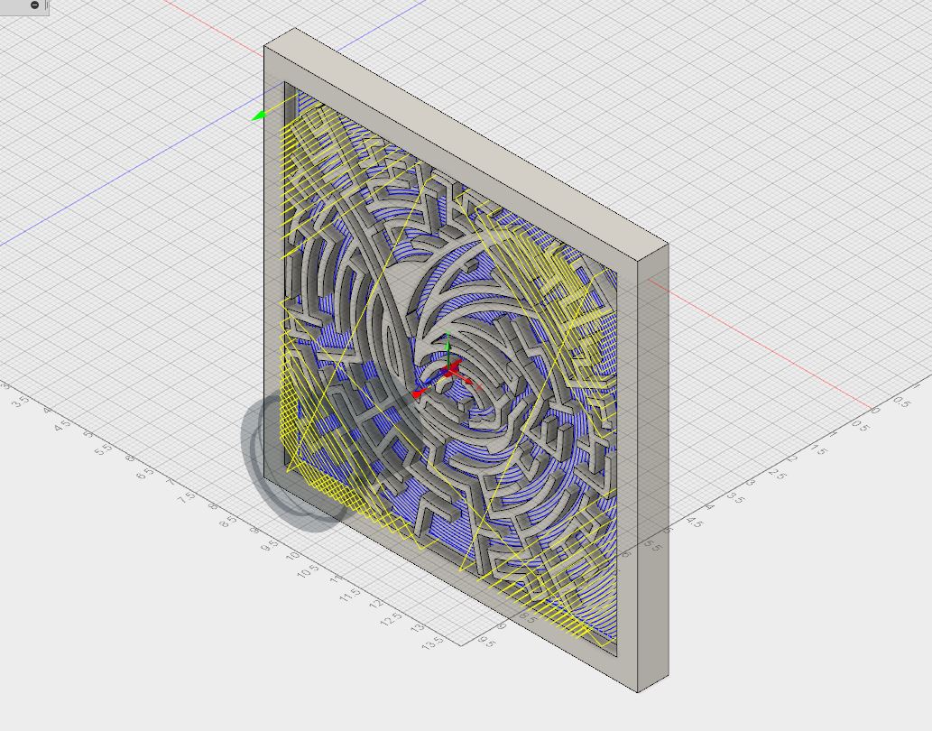 Now I have to tell the router to cut the outer edge of my maze. To do that I can use 2D Contour which is under the same 2D menu as Adaptive Clearing . Then I go under the geometry icon, selected the outer edge of my maze and clicked ok. 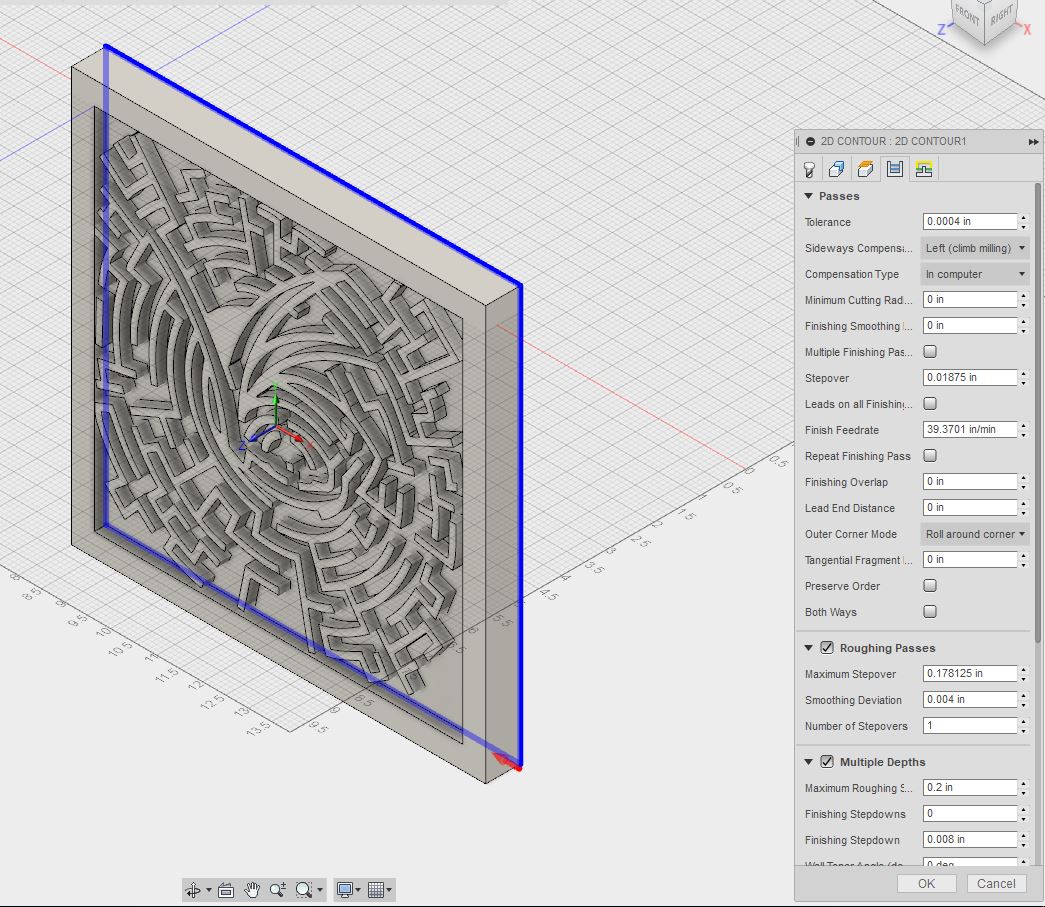 Here are the final toolpaths... 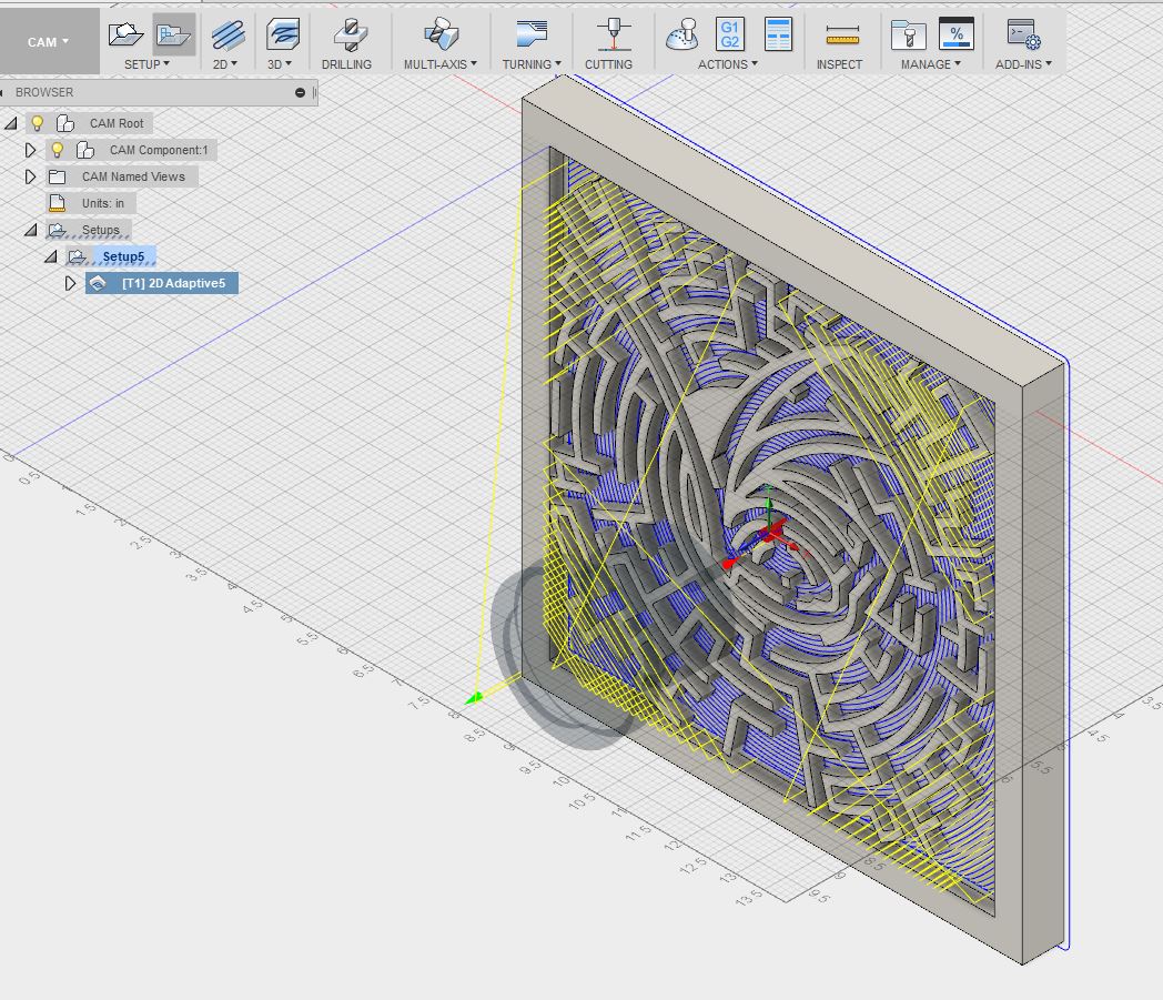 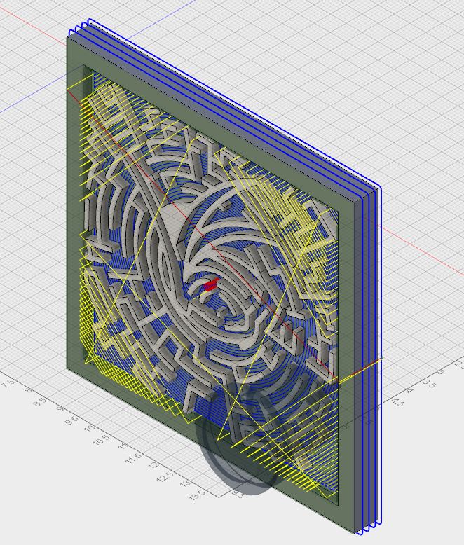 Then I go to the simulation icon and check to make sure everything is cut out that I want to be.
Transferring File to CNC RouterNow I need to translate my toolpaths from Fusion into a language the CNC Router can understand. I go into post process for this, and post the gcode using the Forest program Mr. Willouer downloaded on my computer. Below is all of the lines of gcode that will be transferred to the router. I save this to a flashdrive and bring it down to the computer attached to the router. 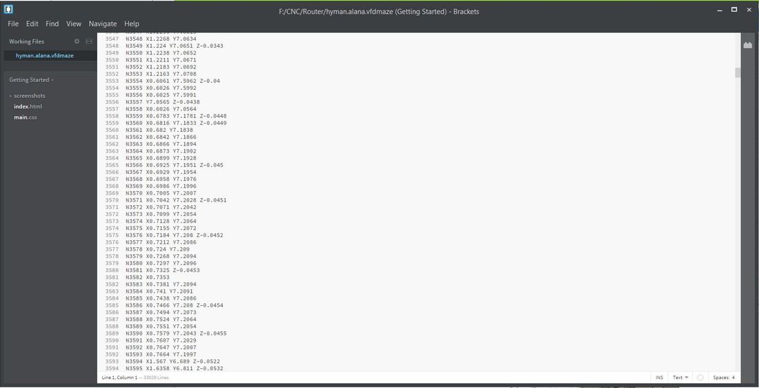 On the computer, to upload the gcode, go to file, import gcode and the program will load for a little while. While I waited I applied a strong double sided tape to my piece of styrofoam I was going to use for my prototype. 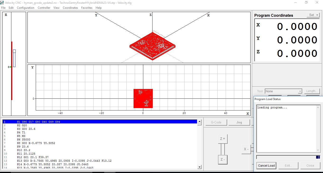 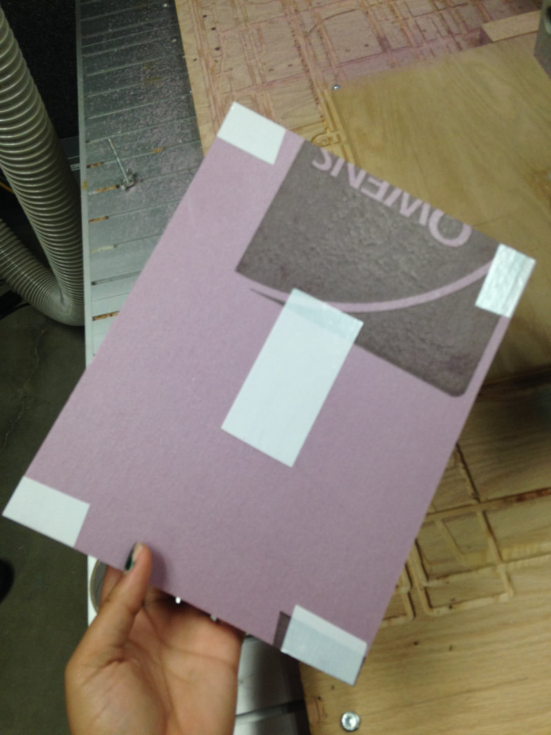 RoutingOnce my file is fully uploaded, I stick my styrofoam piece with its corner edge flush to the right edge of the wooden board closest to me. Then I go to "jog" and move the the drill bit to that same corner. 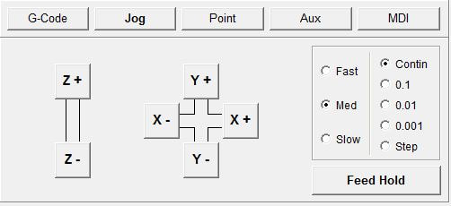 Then I can click start, and let it run! (If anything goes wrong I can hit any key and the bit will stop moving, but for it to stop moving I have to go under "aux" and turn the spindle off). 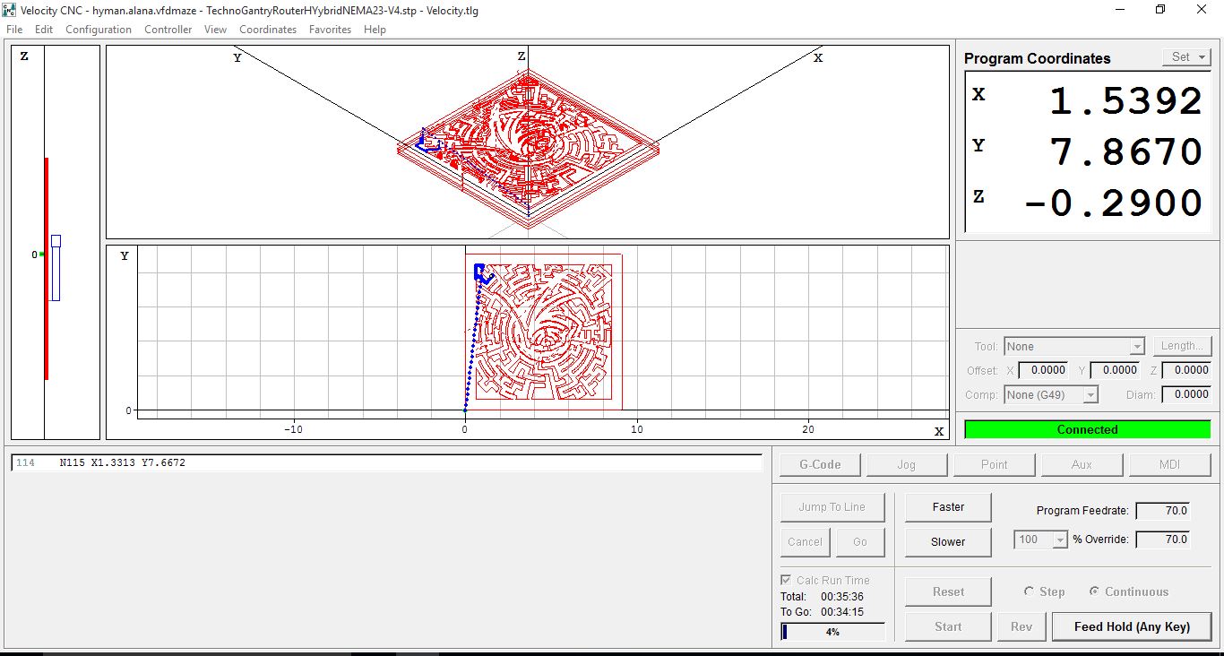 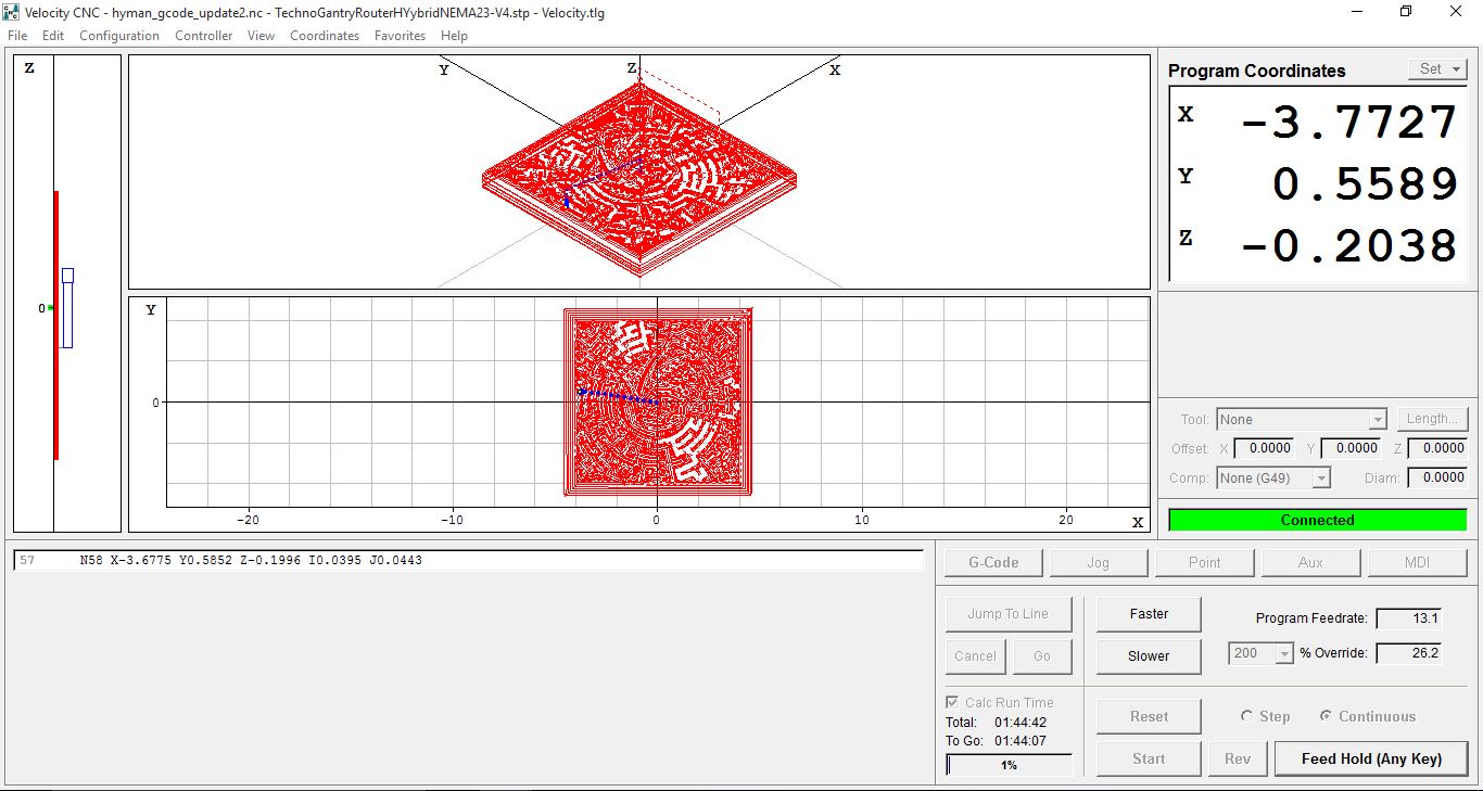 Here is my maze mid-cut... 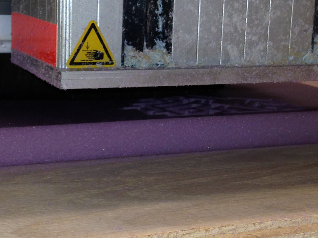 And it's finished! I might cut it out of wood on a later date, but as long as I have the file saved in Fusion 360 I'll always have it ready to go. 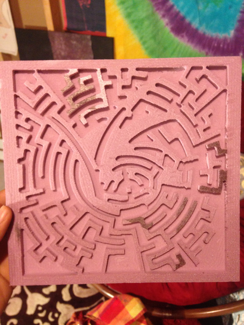 What I LearnedIn doing this project I learned how to use Fusion 360 in collaboration with the CNC Router. I also taught myself how to extrude an image in Inventor, by converting it to a DWG file in Illustrator, which was something even my teacher didn't think was possible :). I also learned what some of the different 2D toolpath functions actually do, which will help me if I use this in the future because if I know how I want the router to cut something out I can now choose the correct clearing or contouring method.
0 Comments
|
What is the CNC Router?The CNC Router (Or Computer Numerical Control router) is a computer-controlled cutting machine related to the hand held router used for cutting various hard materials, such as wood, composites, aluminium, steel, plastics, and foams. What is Fusion 360?It is a cloud-based CAD tool for collaborative product development. Fusion 360 combines fast and easy organic modeling with precise solid modeling, allowing you to make manufacturable designs.
ArchivesCategories |


 RSS Feed
